Overview
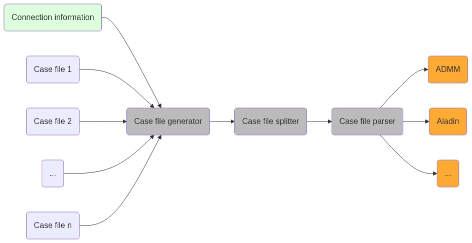
The code consists of three main blocks, listed in the following table.
| Name | Function |
|---|---|
| Case file generator | Merge several case files & connection information |
| Case file splitter | Adjust case files to account for core and copy nodes |
| Case file parser | Generate mathematical problem formulation |
Their relationship is shown in the following:
The interface of the blocks is made up of matpower case files.
This allows to leverage all of the built-in functionality that comes with matpower.
Visualizing case files
There is an exquisite open source tool for visualizing case files: simply drag and drop a valid case file and be merry.
Specifically the input to the case file generator consists of several case files and their connection information; the connection information encodes who is connected to whom and by what kind of transformer. The output of the case file generator is, again, a case file, which is then fed to the case file splitter. The splitter adds information to each individual case file about neighboring buses. This is then fed to the caes file parser (in the form of a case file) whose output is a mathematial problem formulation in terms of function handles. The case file parser also generates sensitivities of the power flow problem.
Allowed connections
Systems can be connected in arbitrary ways at generation buses, for instance:
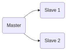
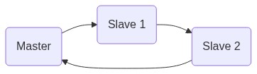

There may be several connections between two systems too.

Warning
It is currently not supported to connect several lines between the same buses.