Assumptions
Naming convention
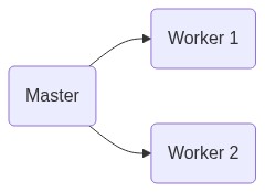
We distinguish between a master system and several worker systems. The sole difference is that the master system contains the reference bus.
Case file generator
- The slack bus of the master system is the slack bus of the overall system.
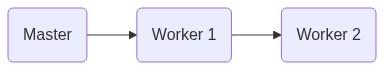
- Systems can be connected in arbitrary ways at generation buses (i.e. slack buses and/or PV buses), for instance:
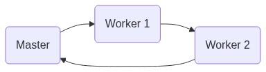
- There may be several connections between two systems too.
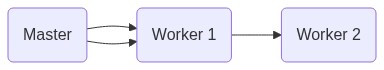
Warning
It is currently not supported to connect several lines between the same buses.
- In the to-system we replace the generation bus by a
PQbus with zero generation and original demand. - If the connecting generation bus in the to-worker-system is the slack bus, then this slack in the worker system is replaced by a
PQbus with zero generation/demand. - On the other hand, if the connecting generation bus in the to-system is a
PVbus, then thisPVbus is replaced by aPQbus - If no connecting bus in the to-worker-system is the slack bus, then the worker system’s slack bus is replaced by a
PVbus; the respective set points for the active power and the voltage magnitude are taken from theMatpowercase file entries inmpc.gen. - If the master system has N_{m} nodes, and if each worker system i has N_{s, i} nodes for i \in \{ 1, \dots, d \}, then the overall system is going to have N = N_{m} + N_{s_1} + \dots + N_{s, d} nodes.
- The entries for the generated active/reactive power from the fields
mpc.gen()are ignored. - The numbering of the overall system (= master + workers) goes from 1 to N, where N is the number of buses in the overall system, see above.
- The master system contains bus numbers 1 to N_m. The numbering of the buses in the remaining systems is done according to order of appearance.
- All case files have the same
baseMVA. - The voltage magnitude settings in
mpc.genmust be equivalent. - If there are several generators at a single bus, then their voltage magnitude must be the same.
Case file splitter
- The copy buses of each region i are added at the end of the list of core buses of region i. Both the list of copy buses and the list of core buses are sorted in ascending order.
- The bus admittance matrix of region i is created by first splitting the case for region i including the copy buses, and then calling
makeYbus(built-inmatpowerfunction).
Case file parser
- The distributed problem is obtained by copying buses at the connecting lines, and then enforcing consensus at the original buses and their respective copies.
- The state x_i in every region i is composed of n_{i}^{\text{core}} core entries and n_{i}^{\text{copy}} copy entries, where
x_{i}^{\text{core}} = ( \theta_i^{\text{core}}, v_i^{\text{core}}, p_i^{\text{core}}, q_i^{\text{core}} ) \in \mathbb{R}^{4 n_{i}^{\text{core}}},
- and
x_{i}^{\text{copy}} = ( \theta_i^{\text{copy}}, v_i^{\text{copy}}) \in \mathbb{R}^{2 n_{i}^{\text{copy}}}.
- The full state of region i is x_i = (\theta_i^{\text{core}}, \theta_i^{\text{copy}}, v_i^{\text{core}}, v_i^{\text{copy}}, p_i^{\text{core}}, q_i^{\text{core}}) \in \mathbb{R}^{4 n_i^{\text{core}} + 2 n_i^{\text{copy}}}.